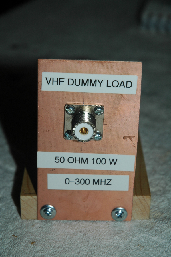
As a HAM Radio enthusiast I like to think I can design, build and evaluate RF Antennas. To help me calibrate my SWR meter I decided to build a VHF 50 ohm dummy load. Naturally, an ideal dummy load is purely resistive (no reactive component).
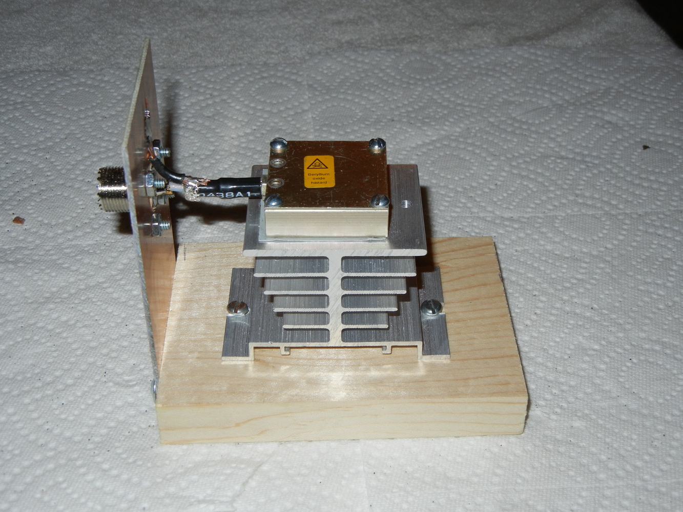
I visited my local Electronics Surplus Store to purchase a 50 Ohm, thin film Beryllium Oxide (BeO) resistive load. Ceramic wire-wound resistors were cheaper but they react more like RF inductors. In general, BeO loads are rated for 3-20GHz and 5-200W, but of course we must never exceed the max rated temperature, 100C (?), so a Heatsink is required. My surplus shop also sold an SO-239 panel mount connector. This is a common VHF/UHF (0-300MHz) connector used in radio communications. Resistor, connector and heatsink component cost was about $15.
The heatsink is resourced from an SSR (Solid State Relay). SSRs are rated for 40W continuous. Be careful. Watch the temperature! A nearby fan may marginally cool. A flexible thermal pad is installed between resistor body and heatsink for better thermal contact.
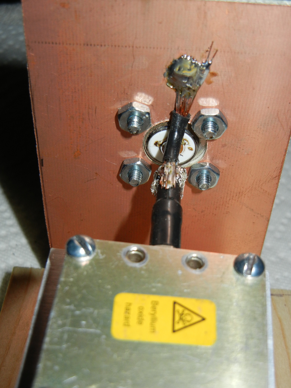
To complete the ground circuit, 14 gauge multi-strand wire is soldered to resistor coax shield and PCB (and SO-239 connector shield). Luckily the resistor shield was not Aluminum.
I tested this with my 75W 2 meter ham radio rig. Works well but at full power it gets hot in a few seconds. I’ll use this load to calibrate my SWR meter readings.
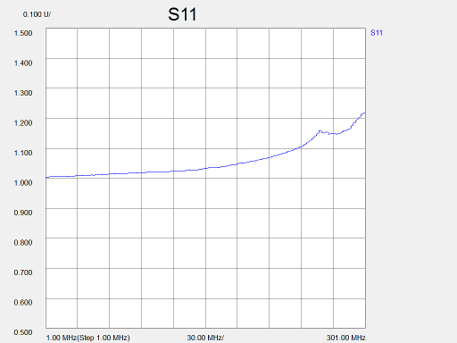
Using a Network Analyzer, I gathered performance data over the frequency range of 0 – 300 MHz. Above is shown Standing Wave Ratio plot. SWR ranges from 1.0 (ideal) to 1.3 (good) at max frequency.
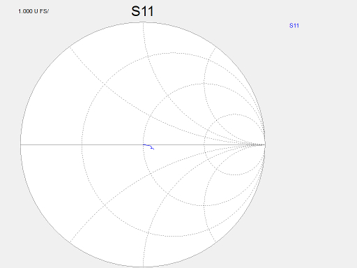
Smith Chart above shows that the load impedance (blue curly-q) is close to ideal 50 ohm resistance over the frequency range.
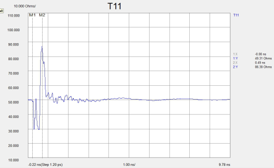 In this Time Domain Reflectometry (TDR) plot the grossly soldered connector is obvious as it ranges from 30 to 80 ohms near the connector. Nevertheless the performance at lower frequency is OK.