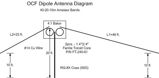
A procedure for tuning Standing Wave Ratio (SWR) of a simple dipole antenna, by trimming wire length, is presented here with empirical data. This is a follow-up to a previous post about design and construction of an off-center fed dipole antenna for the HF Amateur Ham radio bands. ocf-hf-dipole-antenna-diy
Antenna Analyzer
To aid the tuning process I acquired a RigExpert AA-54 Antenna Analyzer. This instrument can easily log Freq, R, X data, over a USB cable, using the AntScope product application software. Then CSV formatted data is imported into an Excel spreadsheet for VSWR calculation and plotting.
Trim Length
SWR tuning is performed by snipping short lengths of antenna wire, at the farthest ends, in order to raise the resonant frequency to within a desired frequency range. Fortunately there is a simple, accurate, formula to calculate the trim lengths. Consider:
c = L1 * F1 = L0 * F0
Where c is the speed of light, F is Frequency and L is Wavelength, 0 subscript is the initial and 1 is the target case. Using some algebra we derive Trim_Length:
Trim_Length = L0 – L1 = L0 * ( F1 – F0) / F1
For example, raising the resonant frequency of a 65 ft. dipole from 7.0 to 7.3 MHz:
Trim_Length = 65 ft. * (7.3 – 7.0) / 7.3 = 2.67 ft.
For this case, where the antenna is fed in a 1/3, 2/3 off center ratio, the trim lengths at each end are respectively:
short_side_trim = 2.67 ft. / 3 = 0.89 ft.
long_side_trim = 2 * 2.67 ft. / 3 = 1.78 ft.
Trim Results
I’m somewhat risk averse because shortening wires is easier than lengthening them. Optimizing performance on several bands can be tricky so I trim the wires in small increments, and measure the results across the relevant bands at each step.
The plot below shows the SWR performance across the entire frequency range for the AA-54 Analyzer (i.e. 0-54MHz). Note the original length “1st” and trim lengths of -6, -15 and -17 inches
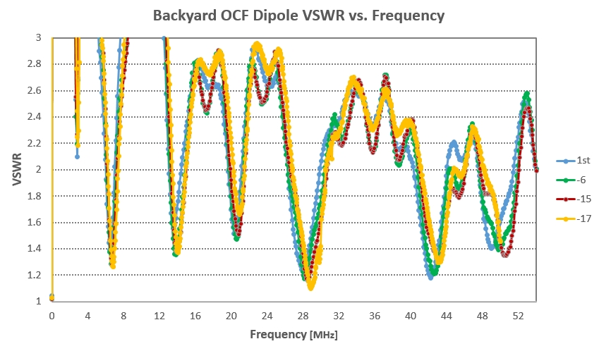
Local SWR minimums are noted at the 40m, 20m, 15m and 10m bands. Local minimums are observed around 43 and 50 MHz as well. 43 MHz is not usable for Amateur operators and 50MHz (6m) is somewhat marginal and not interesting to me now.
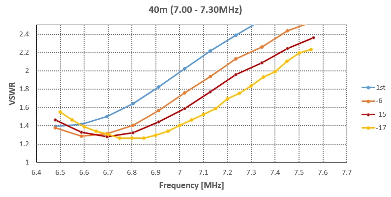
Focusing on the 40m band, the effect of trimming can be measured at each step. Each incremental trim raised the resonant frequency and after trimming 17 inches, SWR ranges from 1.4:1 to 1.8:1 across the 40m band (7.0 – 7.3 MHz) (yellow).
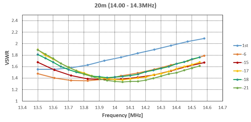
Similar results are shown for the 20m band. After 21 inches trimming VSWR is a nearly ideal (1.4:1) across the entire band. Considering the effect of trimming on other bands I stopped trimming here. 21 inches is somewhat less than the predicted 2.67 ft. (32″) but close enough for practical purposes.
A Z-normalized Smith Chart below shows the impedance across a range of frequencies in the 40m and 20m bands. Black markers are at mid band. The lowest SWR, nearest the center, for both bands, is found at about twelve-o’clock in the chart.
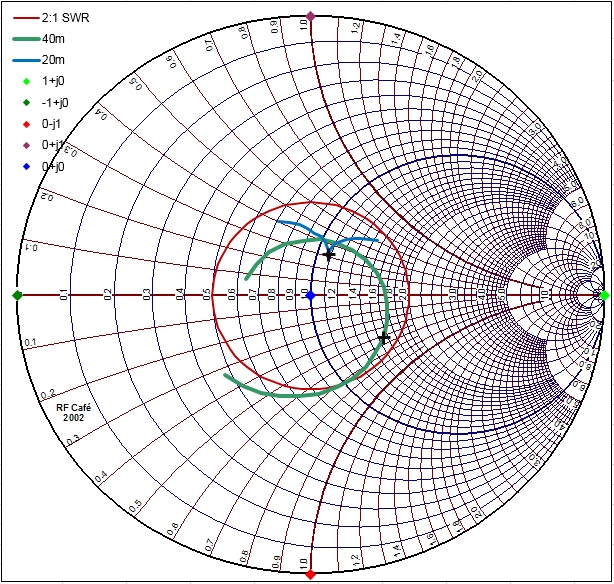
A circle of constant 2:1 SWR is shown in red.
SWR vs. Reflected Power
The motivation for trimming dipole wires is to match the antenna’s impedance to the transmitter output impedance, in this case 50 ohms real resistance. When matched, the reflected wave is minimized and power radiated by the antenna is maximized. So how low a SWR is good enough? Below is a plot of SWR versus reflected power.
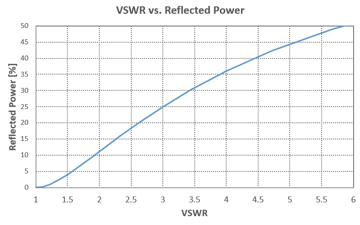 As shown, a 3:1 SWR reflects 25% power, 2:1 SWR reflect about 11% and 1.5:1 reflects just 4%. Therefore a 2:1 SWR or better is generally regarded as “tuned”.
Conclusion
- An Antenna Analyzer was a useful tool for measuring complex impedance across a wide range of frequencies (outside amateur bands). With this data, VSWR was calculated and a strategy formulated to improve performance.
- I discovered a new usable amateur band on 15m. This bonus band was not anticipated in the original design. In fact I have made several QSOs throughout the USA using this band.
- As initially constructed, the length-measured antenna wires were close to the design goal but SWR improved substantially after trimming.